Wednesday 14 June 2017

(10) Tram - Let's make some steam & (nearly) final wiring diagram

This blog will be all about the electronics that drive the tram. It is a bit more text heavy so apologies, although there are a couple of videos!

A lot of the electronics were built during the summer holidays, however throughout the year bits have been added and also removed. Below is the wiring schematic so far, but before we get to bogged down lets look at all the components including the newest part, which was an impulse build - the steam box generator.

I have to say this was not completely my design, and there is a fantastic DIY guide to follow if you wish at the below address:

http://www.wicksteedparkmbc.com/smoke-generator.html

The main difference between the two designs is the water container and how it is controlled, but more on that later.


Here is one of my early prototypes, after changing the water container a couple of times due to not being enough space for the mist to collect above the water. It is a simple design with a PC fan creating draft, which pushes the water vapor up and out of the plastic tube. I also looked at what difference having different sized fans made to the effect.


Here is the test footage, which shows it doing a pretty good job. This is when I started to think how the effect would be vastly improved by having a variable speed, so the faster the motor is going, the more 'steam' is produced. This led to me to test running the fan from the connection which powers the motor, and it worked great - apart from one issue! With this setup, the PC fan sped up and slowed with the motor, but now when the tram is stationery the fan would switch off, producing no 'steam' at all. I played around with the idea of having two fans, with one permanently on and mounted above the other. Another problem I had was the PC fan produced far to much draft when the tram would be stationery. This took me a couple of hours head scratching, but then I had a brain wave.


And this was it, a simple 24V Relay. Check out the wiring diagram below, but the basic idea was to have two power supplies running to the fan, one that was constantly on as soon as power switch was turned, and the other running off the motor power supply. This also powered the magnetic coil, so when enough voltage was applied, it would switch the relay and supply the power from the motor. This worked great, but I was still having the issue of to much draft, which was simply solved by adding a potentiometer into the 'always on circuit' allowing me to adjust the speed of the fan at stationery.


I popped it all in a (very tight fitting) project box. I also added a switch which the fan and misters are wired to, so I can switch the smoke generator off and still run the tram if required.


And this is the final design. The space within the tram is very snug, seeings as I have two batteries (running a 24V system), vs the original design running from one battery (12V system). This led to an interesting dilemma of being able to fit a water container that also had enough space to mount the PC fan. This led to an L-shaped box which was laser cut panels glued together, with a clear acrylic lid on top. A second mister was also added to help produce even more 'steam'.


And this is it, in this video I show the variable speed just from adjusting the potentiometer rather then using the relay and the motor speed controller. The only reason for this is I only had one hand free and it was easier! Once the main body is built and rolling I will post a video showing that circuit working.

This is the circuit diagram you have been waiting for. Apologies for it being rather crude, but I designed it really for the school parents day, and wanted to make it as easy to understand for students and parents as possible. I have separated the main electronics and the newly added smoke generator, just to make it as easy to understand as possible as it has nearly as many components as the main circuits! I think it is pretty straight forward, but let me know if you need any more information.


Friday 2 June 2017

(9) Tram - Building the bodywork

The bodywork began by using the dimensions from the 'Going Electric' article (below), but updating them for my design.


Going Electric Article


I used this information to design a CAD drawing, which i could use to produce plywood templates on the laser cutter, including the final design for the control board


My next step was to produce the beach blanks that would clad the entire body. I began by ripping some strips of scrap Beech on the table saw down to 5mm


Another shot of the strip ripped down with the plywood jig behind


This then needed to be thicknessed down to the correct dimension of 3mm and to remove any saw marks. To do this each strip was stuck on to a crap piece of plywood with our CNC double sided tape. They could then be fed through until the exact thickness was achieved.


The strips were then passed back through the table saw to produce planks of the correct width


Showing some strips all cut to the same thickness and width


The last step was to pass them under the overhead router. This was done to produce a slight bevel along the two long edges, which creates a more realistic plank effect when they are stuck side by side. A similar process was done to produce the square framing section.


A snapshot of testing the laser cut plywood body panels 
 

Testing the correct thickness of the planks against the body


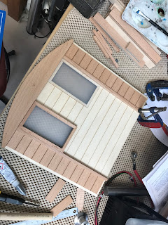
Beginning to glue on the planks which have been cut and sanded to size
   

The finished front end of the Tram with the light fitted


The new control unit being glued up


The nearly finished control panel (just missing the horn button)


Picture with side panel half glued up.


Nearly there - one more side to go!

Friday 21 April 2017

(8) Tram - It's all about those buffers

This post is all about manufacturing the buffers. Below is the beginning of the drawing which I updated into mm ready for turning. 


Dimensions half way through being converted (to make it easier as I have multiple buffers to make)


This is the buffer head, which has been taken from a round bar. I have already faced off one end, center drilled and I am now drilling it to the final tapping size


Tapping the buffer head


It has now been screwed onto a bar which I had previously put a thread on. This is the blank that can now be turned true


Turning down the outside of the buffer head


By setting the cross slide at a particular angle (15 degrees), the profile of the buffer head can be seen to be taking shape
 

The buffer now in the jaws, with the shank cleaned and ready for the steps to be turned


The final buffer ready


 I have now moved onto looking at the buffer casings. Taking a round bar I created the profile required using a variety of tools


Another picture of the profile more complete


The profile complete, center drilled awaiting final stepped drilling 


Drilling in progress


An 'Exploded' image showing how the buffer all fits together


The buffer dry assembled inside the buffer case


A hole in the frame has been drilled, tapped and the buffer casing is then screwed into place and finished with a nut (not pictured).


The finished buffer in place

Wednesday 8 February 2017

(7) Tram - Getting the wheels turning, Hook fitting, 3D Printing & UniPart Rail


A few things have happened over the last couple of weeks.
I have started to get the wheels turned from the blanks, 3D printed a case for the control unit, and also went on a great tour of the facilities of UniPart Rail!


Wheel clamped in the center lathe with the profile started.


Showing the wheel out of the lathe and how it is still over sized.


Filling the hole that was drilled to take the front hook


A 3d printed case which has been designed to house all the speed control electronics


The first poster in UniPart Rail describing all that they construct and repair


Inside a points control unit


A finished crossing warning light ready to ship


Overhead power unit that is used on the EuroTunnel crossing


Wednesday 1 February 2017

(6) Tram - Holiday snaps, Grateful Gifts & Some Axle Boxes

We recently went on a holiday down in Devon and stumbled across a brochure for a round Robin tour including Boat, Bus, Steam Train. If you are in the area well worth a visit! http://www.dartmouthrailriver.co.uk/tours/round-robin


Totnes puzzle postcard.


The Dartmouth Steam Train (Lydham Manor).


A piece of display 5" Track which has been kindly loaned from the previous Technician for when the frame / chassis is complete to run along.


The beginning's of the axle boxes. They are machined from a square piece of aluminum, and then using the milling machine the slots were cut.


Another view of the milling machine with the cutter in the foreground.


Once the slots are in place, it was over to the center lathe for parting, facing off and drilling. Pictured is the center drill being used. Once the hole was drilled a reamer was used to get the hole perfectly round and to the correct size.


The Axle box covers are cut by hand and then filed to the profile of the axle boxes. They are then drilled for a M2 bolt using a mini pillar drill for complete control.


Axle boxes being tapped for the M2 bolt


The last step is to push fit the Oilite bushings in ready for the axles.